
PROGRESS LOG
Week 12
7/22 - 7/28
The group worked on finalizing the website for the professional engineers to view. We added videos and graphs to the Testing and Results page.
We worked on our presentation.
Week 11
7/14 - 7/21
During this week the group worked on completing the Design Report and some final testing for the code. The testing results for the project are shown below along with a graph showing the success and failure rate. Part of the testing for the project included scenarios which would test the object detection software on speed of detection and certainty. Other scenarios tested ranged from a person waving their hand over the pool to a person running from out of frame into the pool. The main focus was to see if any misfires would trigger the alarm when performing these tests.
Figure 1

Figure 2

Video demonstrating the operation of the LEDs.
Week 10
7/06 - 7/13
During this week the group tested the software at the pool and took samples of the results. We had many hours invested in troubleshooting, as was expected. The pool we had originally tested on was unavailable over the weekend (7/10 & 7/11) so we transitioned to a different location. The wifi at the new location was spotty therefore a wifi hotspot on the phone was used instead. After getting the code functioning as expected we tested the system little by little, starting from the beginning of the process to make sure each component was responding as it should. After our first successful trial, we ran 4 more tests and video recorded them to capture the success in action. Below, in Figure 1, you can see the video recording of one of the four trials.
Figure 1
The exterior of the housing for the Pool Pal was constructed and assembled. The parts were fit into place to gather an idea of what the finished product will look like. The exterior, made of cardboard, was painted and fit onto the frame. You can see the prototype in Figure 2.

Figure 2
Week 9
6/25 - 7/05
The group has completed the code for the app and the project. Work on the paper has begun and the team has completed most of chapter 1. In the coming days the team will record the final video demonstrating the project and its functions. Below in Figure 1, is a look at what the user will see when accessing the app. The stream of the video will be displayed on the top and at the bottom there will be options for the user to choose such as Arm and Disarm, Calibrate, and a shut down function.
Figure 1

Week 8
6/18 - 6/24
The group met up at the pool to do more testing.
For the first experiment, we needed to test the new model of the PIR motion sensor. Reviews online for the potentiometer PIR model were poor, so we went with a smaller lighter model that had no potentiometer. Controlling the sensitivity of the PIR was done through software by controlling a threshold value. The threshold value is a decimal between 0 and 1; the default being 0.5. Below were our results from testing.
-
Threshold @ 0.50: ~10ft range
-
Threshold @ 0.25: ~24ft range
-
Threshold @ 0.10: ~41ft range
The width of the PIR was also tested. Circling around the pool the PIR picked up motion from all directions. A distance of 10ft from the pool's edge is adequate enough for the PIR to detect motion.
Next, the custom model was to be tested for the first time. The training of the model took 1hr and 18min given 114 images @ 10,000 steps. Without a GPU the training took 96% of the CPU resources and froze the pc until the training had finished. However, the model performed surprisingly well! No output pictures were taken since there will not be a visualization of the detections. For our purposes, an LED and buzzer served as an insight that a person had crossed the pool's boundary.
Following the test of the custom model, the group's intent was on taking more sample pictures for the visualization of the detections. Unfortunately, the PiCam resource was unable to be accessed throwing an error on the console. The cause of the error was due to allocating GPU memory to the CPU, on the Pi, for faster detection. But, the camera relies on the GPU memory for proper operation. For this reason, we had to revert back to the default GPU memory size.
After testing at the pool was complete, the group went indoors to perform further testing of code that broke during the pool tests. The PIR sensor was tested alongside the LED and buzzer so that the group may create a finalized circuit layout on the breadboard. Below, in Figure 1, we show the video of the test.
Figure 1

Next, the frame of the housing was constructed. The design was chosen to be as small as possible while still fitting all of the necessary components (and with room to spare for long wires/cords). The length, width, and height of the housing (without panels) came out to be 7_5/8'' x 4'' x 4''. Proper wood adhesive and clamps were used to make the structure as strong as possible. Stress tests will not be performed. Pictures of the build process shown below in Figures 2 and 3.
Figure 2

Figure 4

Figure 3

Figure 5

Week 7
6/11 - 6/17
The group has made minimal progress over the past 7 days. Part of this is due to the custom machine learning model we are building; the libraries and dependencies required for the training have proven difficult to install and set up. As of yesterday, June 23rd, we were able to make progress on the training of the model but not enough to show tangible results. We predict another 4 or 5 hours will give the results that we expect and testing can continue as planned.
Objectives we strive to achieve for next week will be to start building the housing, compile code to one source, and test our custom model to see if our model needs tweaking. We also plan to have a healthy amount of the report written for review.
Week 6
6/11 - 6/17
The group got together to test the effectiveness of the buzzer and motion sensor. Simple operation tests were made indoors to make sure the code ran as expected. Surprisingly, the buzzer was louder than expected. More tests need to be conducted at the pool to determine the effective range of the motion sensor. Figure 1 and Figure 2 show the buzzer's setup and operation.

Figure 1
Figure 2
The task of using the pool contour for object detection was accomplished using the following techniques. Figure 3 shows the original image used to test this method.
-
Crop the photo of the pool at the coordinates saved in memory from calibration, as seen in Figure 4.
-
Translate the points of the pool's contour array in relation to the top-left coordinate of the pool.
-
Create a binary mask by interpolating between array points. This created a polygon that was filled in with white, as seen in Figure 5.
-
The bitwise AND operation was used to combine the cropped image and the mask. The result can be seen in Figure 6.
In the calibration stage, along with saving the pool coordinates, the pool's contour array must also be saved. The calibration script was updated accordingly. The final resulting image, in Figure 6, will be the image used to apply object detection. As you can see, the pool is surrounded by black; any object that is not directly in the pool will not be considered.
Figure 3


Figure 4
Figure 5
Figure 6
Week 4&5
5/29 - 6/10
The group has chosen to take a different direction with the app. Both members did not have experience with creating native apps on android. For this reason, the decision to make a web app was chosen. The group has much more experience with web-based applications. The advantage of making a web app is that it can be used on android, iOS, and desktop alike. The web app is coded in javascript and uses node.js for serverside requests. Figure 1 shows the skeleton of the app, with all the features displayed. The calibration button is functional. The alarm and camera buttons need their terminal functions to be applied to function. The live video streams at 30fps. After the web app is functional, the look and feel of the app will be designed.
Figure 1

The team met up for round-2 of sample images. During this time the pi camera was used. The results from the pi camera were exactly what the group was looking for; a much better resolution of 2592x1944 provides a much better image quality. Satisfied with the camera, an image was tested in the calibration function as seen in Figure 2.
Figure 2

Using the sample images captured from the pool the group made a test model in TensorFlow on the RPi. The object intended for detection was a 'person' object. Samples of the results are shown below in Figures 3, 4, and 5.

Figure 3

Figure 4

Figure 5
Lastly, transitioning from a native app to a web app has its challenges. Ideas for setting off the alert for the user were discussed at great length. Setting off an alarm on the user's phone is a feature that is frowned upon for developers because of the potential risk of spammers; much research was invested into finding a solution. The group decided to use the call and message abilities of a phone as the alert system. Using Twilio, a phone number can be purchased and used to program different Call/SMS features. A python script was written to send a text message to a list of users, as shown in Figure 6, and to call the list of users, as shown in Figure 7. We believe that this is an adequate solution for the alert system.

Figure 6

Figure 7
Week 3
5/21 - 5/28
The team continued working on the video stream and had to work through some issues with the code. The video feed part of the app is making progress as shown in Figure 1. The group has made some progress on the logic for the communication between the app and the micro controller as shown in Figure 2. The image shows some the errors that the group had to solve using Kotlin as a the coding language.
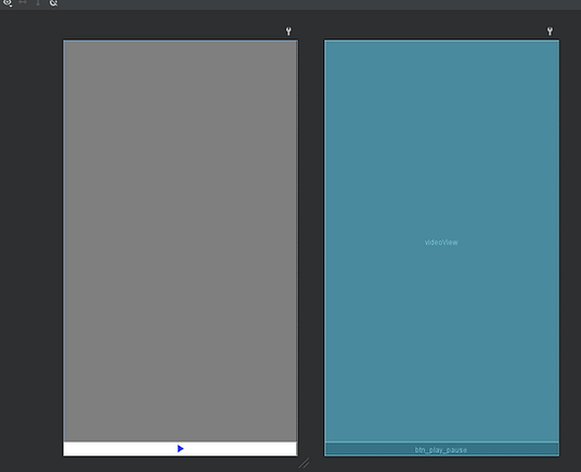
Figure 1

Figure 2
The team set up the RPi headless to operate from a separate computer over a local network. A 2.074-megapixel webcam was chosen out of convenience for use of the built-in microphone. Using the Motion RPi add-on, the group is able to stream live video at 30fps over a local area network. With video streaming complete, 2 scripts were written to takes pictures of the pool. The first script is for taking a single picture to feed into the calibration function. The purpose of the second script is to take sample pictures of a pool with multiple detection scenarios. The results of some of the sample pictures are depicted below in Figure 3 and Figure 4. Measurements of the pool were taken to determine the hypotenuse distance from the camera to the farthest edge of the pool, equalling roughly 40.5 feet. Samples were taken on May 25th at 2:50 pm.

Figure 3

Figure 4
Problems arose when examining the sample images. At 100% image size the pictures were very blurry and when zooming in there is obvious pixelation. This occurred merely at the middle of the pool and not at the maximum distance. This motivated the group to switch cameras. Instead of using a webcam, the group intends on using a PiCam v2.1. PiCam is an 8-megapixel camera with more functionality and control over the images. The scripts were rewritten to accommodate the change of hardware. New sample images need to be taken to analyze the resolution of the new camera. In 2020, Raspberry Pi released their new PiCam HQ which has a 12MP sensor and interchangeable lenses. If the picture quality still isn't up to spec, the group intends on upgrading the camera. This upgrade will not affect the code since they're both PiCam's, therefore testing will continue with the PiCam V2.1.
RPi/App communication is a vital part of the project. Apache2, PHP, MySQL, and phpmyadmin were installed onto the RPi to create a server, edit the server, and creates databases to store information over the web. This will allow the user to change properties of the RPi code over the internet through the app.
Week 2
The team began working on the app and software of the project. A simple layout of the interface of the app was drawn on paint to determine how the app will look roughly as shown in Figure 1. Then the group began designing the layout with Android Studio and using Kotlin as shown in Figure 2. First the buttons were designed with text explainations. The group now is moving towards adding the streamed video in the app.


Figure 2
5/13 - 5/20
Figure 1
The team began the implementation of detecting the pool. The method to achieve detection of the pool is by converting an image of the pool to HSV (Hue Saturation Value), create a binary mask, implement noise reduction, apply a threshold, find contours of edges of the thresholded image, determine areas of each contour, filter contours based on the area (width*height), obtain the bounding box around the contour to retrieve x,y,width,height, then use the bounding box to determine coordinates of the pool relative to the image.
An Object-Oriented Programming (OOP) approach is being taken to keep code organized and concise.
3 examples of the pool-detection are depicted below.
Ex. 1

Ex. 2

Ex. 3

Week 1
5/05 - 5/12
Research has been made to progress the team into a better understanding of how the project will be formed. One of the main concerns is the processing power of the microcontroller. The processor of the microcontroller will dictate the overall quality and results of the project. For this reason, the Teensy is considered for our project. Another product on the market considered for our project is the OpenMV cam, which has a built-in 480MHz processor and functions specifically for image processing. Another addition may be to add TensorFlow API to be able to optimize our image processing accuracy and capabilities.


